
Forums › Knowledge Base › AP Motor Discussion – Certified › Loki M3000
- This topic has 47 replies, 7 voices, and was last updated 16 years, 7 months ago by
 Adrian.
-
AuthorPosts
-
2009-06-28 at 4:39 am #50677
 Chad
Chad
Seems like before you get to the fin material, elasticity, strength, etc, you need to figure out if you are going to keep the fins behind the mach cone (71 degree sweep at Mach 3) or stick them into the supersonic flow, in which case you want a sharp LE and relatively mild sweep back. This will dictate how much leverage is out there and nail down one degree of freedom for you flutter analysis.
I’m just throwing out questions, I don’t have answers, but what about a pronounced spanwise taper to the fins, like .300″ at the base and .004″ at the tip, with a lightweight core? That would hurt a bit in the subsonic realm, but would add strength with little additional drag/flow compression at supersonic speeds.
2009-06-28 at 4:46 am #50678Chris LaPanse
They should definitely be within the mach cone, IMHO. Even if you assume a ridiculously short rocket (say, 1 foot longer than the casing), that allows for something like a 17 inch semi span before you hit the shock wave at the base of the rocket. Of course, the flow will still be supersonic at the fins, even with them inside the shock, and you’ll still want them to have a nice bevel to them.
As far as material is concerned, there’s also premade CF plate – I’d bet this 1/8″ plate would work fine (with perhaps a single t2t layer to hold it on):
http://cstsales.com/carbon_plate.html
Of course, you could get better strength per thickness/weight by making it yourself out of unidirectional CF oriented in specific directions as needed for maximum strength only where it is needed.
2009-06-28 at 6:26 am #50679Chris LaPanse
Well, I’ve put together some rough sims, and even with some fairly bad assumptions, I’m able to get some sims as high as 80k (with something like 40 seconds supersonic) on a 2-stage M3000 to J570, and 42k for a single stage M3000 shot. Admittedly, the 80k is probably a bit higher than is reasonable, but I’d bet the current 45k staged record is well within reach. Of course, with final burnout occurring at 27k and mach 2.8, it would definitely get up there pretty nicely.
2009-06-28 at 7:10 am #50680Chad
I think the leading edge of the wing creates its own shock wave, and not enough sweep creates a lot of wave pressure drag. By sweeping the fin back, the effective mach number- what is perpendicular to the leading edge- is subsonic.
The trade off is a very inefficient lifting surface and more parasitic drag.
Then again, I’m not a REAL rocket scientist.
2009-06-28 at 7:27 am #50681Chris LaPanse
I believe that is accurate, though we only touched on supersonic flight in my Vehicle Design and Performance class last semester. Once school starts up again, I’ll be taking 3000 level aerodynamics, and I could ask my professor about that to see what the best way to go would be.
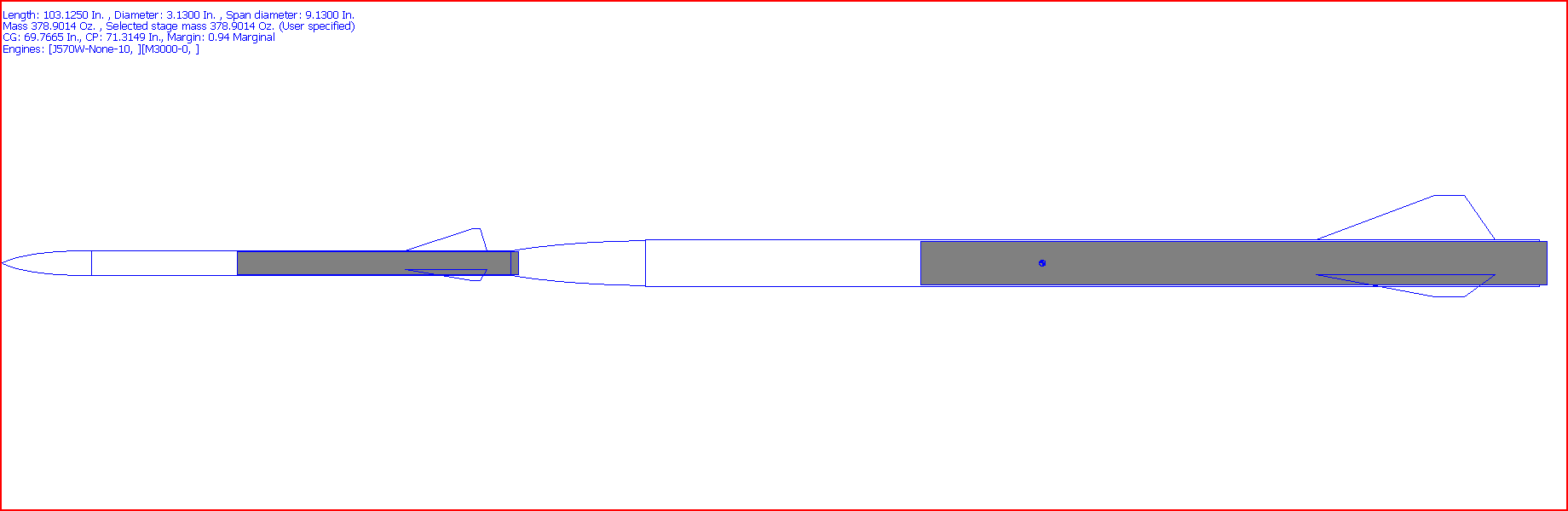
Oh, and here’s my rough 2-stage model:
 2009-06-28 at 1:06 pm #50682AdrianParticipant
Good comments on the fins; the Mach cone angle at M3.5 is about 16 degrees. So these would need to have a really long root chord and short tip length. That alone will do wonders to reduce the flutter risk. Based on my experience with the 0.048″ mostly-uni carbon fins, I think about 0.07″ to 0.08″ thick mostly-uni plate with a couple of layers of tip-to-tip unit carbon over that would have more than sufficient strength and stiffness. But I’d do some calculations first based on hitting some wind shear at M3.5. I’d also need to try to get my hands on some cotronics epoxy so I don’t need to worry about the layup softening due to heating from the skin and motor. Anyone know what sort of motor case temperature to assume?
A 76mm booster to a 38mm sustainer would be an efficient way to get the M staged record, but the transition would be a pain to design and build. Staging 2 same-diameter birds with the motor as coupler (assuming a flush aft closure) makes it really simple. The two sections don’t even need to be designed for multi-stage flight, as long as the sustainer motor can stick out the back and the booster is designed for recovery on a single airframe break. Besides, if you go with a little lower-impulse 75mm M, you have plenty of impulse left over for a decent 75mm K for the sustainer. When the sustainer starts its job at 40k, the drag lost to the extra diameter is not nearly as large as it is starting from the ground. For high-altitude sustainers, ISP becomes more important, just like it is in real launch vehicles.
2009-06-28 at 5:32 pm #50683Anonymous
Gosh, I go camping for a few days and you guys have it all figured out! 😀
Speaking for myself, I’m not interested in a multi-staged project. If this was recovered, then maybe stick a stage below or above it, but I’d (personally) have no interest in staging this from the get-go. But that is me.
Second issue – I have seen some rather elaborate fin cans that were done by highly reputable folks who vacuum bagged, used all the right materials, layers, epoxies, autoclaves, fin shapes, etc. — and their can shredded like it was made out of toilet paper on an eerily similar project. (EX motor, BALLS, couple years ago). Again, speaking for myself – I do not believe we collectively have the skillset or the technology to hang fins on a MD rocket and expect them to stay there on a project like this. I’ve built perhaps 20+ MD rockets, and I’ve never lost a fin. I don’t think I’d have a chance on this one. I think you’d have to go w/ an aluminum welded fin can (which could be below the airframe and as such, out of the airstream).
Anyone do any estimates on what the gees would be on a 3Kg rocket with that much horsepower? Remember, you have to keep a couple of batteries and a couple of sets of electronics intact.
Finally, the other issue with that many gees is propellant stripping away from the liner of the grains and falling into the core, which would be… spectacular (in a wretched sort of way). This is clearly a rocket that may benefit greatly by having more mass – the coast would be unreal, and you’d keep the speed and gees back. I don’t think this is where you’d want to build as light as possible (ping pong ball vs. golf ball).
Sounds like a lot of challenges, but it would be cool to crack 50K. We’ll know soon, I’m sure rockets are already being built to try this motor.
JW
2009-06-28 at 9:30 pm #50684Chris LaPanse
Well, my rough single stage sim to 40k or so with a 3kg rocket would pull around 50G on its way to M3.2. The acceleration shouldn’t be a problem – Adrian’s I powered shot did fine with greater acceleration than that. As for the velocity – I still think that Adrian is right, and a couple of solid carbon plate fins would hold up just fine. I’ll drag out the aerodynamics textbook though to see what kind of forces we could be talking about here, and that might give a better idea of what kind of fins would hold up best.
2009-06-28 at 10:50 pm #50685Chris LaPanse
Well, after some calculations, it appears that 0.083″ fins are all that is needed at a minimum, at least for my design. That is using the assumption of a launch at 4k ASL (black rock, roughly), and that max Q occurs at max velocity. That gives a max Q of roughly 86,400 PSI at Mach 3.3. I then calculated the lifting force on each fin based on a 150ft/s crosswind that is entered at exactly the worst time (at max Q), which gives an angle of attack of 2.4 degrees. Using published lift data from the SR-71 as a good approximation, that gives a lift coefficient of around 0.04, giving a fin force of 72,600 pounds. Assuming that the force acts at the midpoint of the fin (which is actually a worse scenario than what should actually occur), this means that with a fin 0.083″ thick, the maximum stress at the root would be 145 ksi, which is a representative value for aerospace-grade carbon fiber that I could find. Of course, homemade CF would be somewhat weaker, but with 0.125″ thick fins, I get a maximum stress of 97ksi for example. In addition, the maximum stress location is at the root of the fins, so if there were some fairly healthy fillets and T2T, that would significantly reduce the stress at that location, and increase the chance of success.
Also, keep in mind that this is a worst case scenario – specifically, that it hits a 150ft/s wind shear at exactly the point of greatest dynamic pressure. In all likelihood, this would not happen, and even if it did hit a wind shear, it would probably not be this strong. Because of that, I would think that 1/8″ CF plate would be more than adequate to survive this, if it were attached solidly enough (it would probably be best to start with thinner CF plate, and then build it up with T2T). As for flutter? I doubt very much that flutter would be a problem with 1/8 CF plate in a fin with a 12″ root and a 3″ semi span (the design that I am currently running all of my numbers based on).
EDIT:Ignore this post. It contains several calculation errors. For the correct values, see my post farther down
2009-06-29 at 12:31 am #50686Anonymous
Great calculations, but if a layman like me understands the thoughts here, I think you are talking about stress on the fins – not the joints. The joints – not the fins – are what is worriesome. That is why I talked about a welded aluminum can.
I’d still be worried about gees. The toughest fins on earth aren’t worth a song if the bottom grain in the motor collapses due to the weight of the other grains on top of it 😯
Interesting challenges indeed.
-
AuthorPosts
- You must be logged in to reply to this topic.