
Forums › Archives › Archives 2012 › Smash Rocketry New Group Project – The Proton M
- This topic has 391 replies, 29 voices, and was last updated 12 years, 5 months ago by
 Kevin Osler.
-
AuthorPosts
-
2012-01-19 at 7:25 pm #55224
 Jack MatthewsModerator
smashburn – been at this only a couple of years, but did manage my L1 last summer. Have no practical skills, tools, spare parts, or ideas. Schooled as a chemical engineer,, that basically translates to, “Put a blue hardhat on that man and keep him away from the tool chest.”
But I would like to help out (live in Fort Collins) – and as you implied at the annual meeting – learn by watching the big boys. I can sweep floors, change lightbulbs, take out the garbage (my wife can vouch for that), and recently learned how to operate a can of spray paint. Unlike many in this economic climate, I am fortunate enough to be gainfully employed, so have a little disposable income that I could donate to the cause.
Let me know how I can help.
2012-01-19 at 9:25 pm #55225BEAR
I found a bunch more information and photos on the Proton K, Proton M, UR-500, SL-9 thru SL-12 rockets, learned about the Baikonour Cosmodrome, some, really detailed photographs of the rail car and launcher, etc. and thought I was placing it here on the site. It must have timed-out or something because it has not shown up. I am going home this evening and try to recreate it in word, and then cut and paste incase it did time out, and I am going to break it into two parts incase the file was to big. Mr. Webmaster, are these issues and if so, what are my limits?I also found another site for the paper card stock model of the Proton with photographs of the completed sub-assemblies. It showed the staging couplers between stage 1 and 2, and how it fits. Another link that I have to recreate showed a cut-away of the rocket and showed that the main tube that all the motor tubes are attached to is really just an oxidizer tank of nitric tetroxide, and the tubes that the motors are mounted onto are the actual fuel tanks. I will try to put all of that here tonight.
2012-01-19 at 10:08 pm #55226Warren B. MusselmanModeratorI’d just like to say that Steve Mashburn (smashburn) took on a bare L1 (me) when he proposed the Delta II project. I had some skills, but had never been involved in anything like that level of size or complexity. He knows how to execute a large project and I highly recommend it as what may well be one of the seminal experiences of your rocketry career – it certainly was for me. I learned a LOT and had a great time along the way. When it finally flew, my heart was in my throat and I was jumping up and down like a 5 year old. An experience not to be missed.
I’m here and available if needed.
Warren
2012-01-20 at 1:51 am #55227BEAR
Here is some more info. that I have dug up. See if this helps any..
In expanding my research in the quest for more details, I came across this site with a great photo of the rocket on its rail car. (http://www.russianspaceweb.com/proton.html)
My search looks for details for the UR-500 ballistic missile, and the different NATO designations SL-9 thru SL-12 Proton.
At this site, which is a different page of the previous site, you can see the rocket being lifted on its rail car. Note: some of the wheels or trucks stay on the track and are not lifted. (http://www.russianspaceweb.com/proton.html#protonm)
At this website, there are some interesting diagrams and photos. The diagrams show the 1st and 2nd stage fuel tank layouts, which explain some of the design and why it was built the way it was. (http://www.astronautix.com/lvs/proton.htm)
This next site describes the launch complex and Baikonur . It goes into detail of how the rocket it erected at he pad and has a number of good photos that will give detail information. (http://www.russianspaceweb.com/baikonur_proton.html)
There is the paper model again with links to the photos of the finished sub-assembly with information on the staging coupler at this site: (http://jleslie48.com/gallery_models_real.htmlhttp://jleslie48.com/gallery_models_real.html)
Here is the other paper model link for comparison: (http://www.cardmodels-r.narod.ru/index-e.htm)
Here are some photos to give greater insight:
http://www.isdc.unige.ch/images/newsletter/n10/proton.jpg
http://www.spacetoday.org/images/Rockets/Russia/Proton300thLaunchRolloutILS.jpg
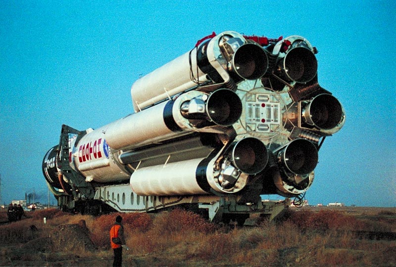
IN this photo, look at the resting cradles. This will be the way to mount rail guides. http://www.spaceistheplace.ca/protonfactory.jpg
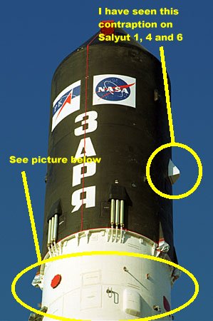
This photo is for the super-scale detail guys: http://www.svengrahn.pp.se/radioind/mirradio/Zaryatop.jpg
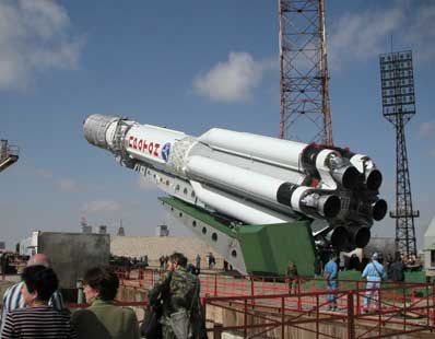
Here is a bigger picture of the rocket being erected. Notice the covering over the staging section. Looks like they use duct tape also! (http://operatorchan.org/v/arch/src/v25429_Russian%20space%20rocket%20Proton-%20Baikonur%20rocket%20base-.jpg)
Still a different paint scheme while being erected and more duct tape! http://4.bp.blogspot.com/-hVisdjakmGA/TnvxQe6Hs-I/AAAAAAAADig/mzlsr_uFum4/s1600/ustanovka-rn-proton-na-pu.jpg
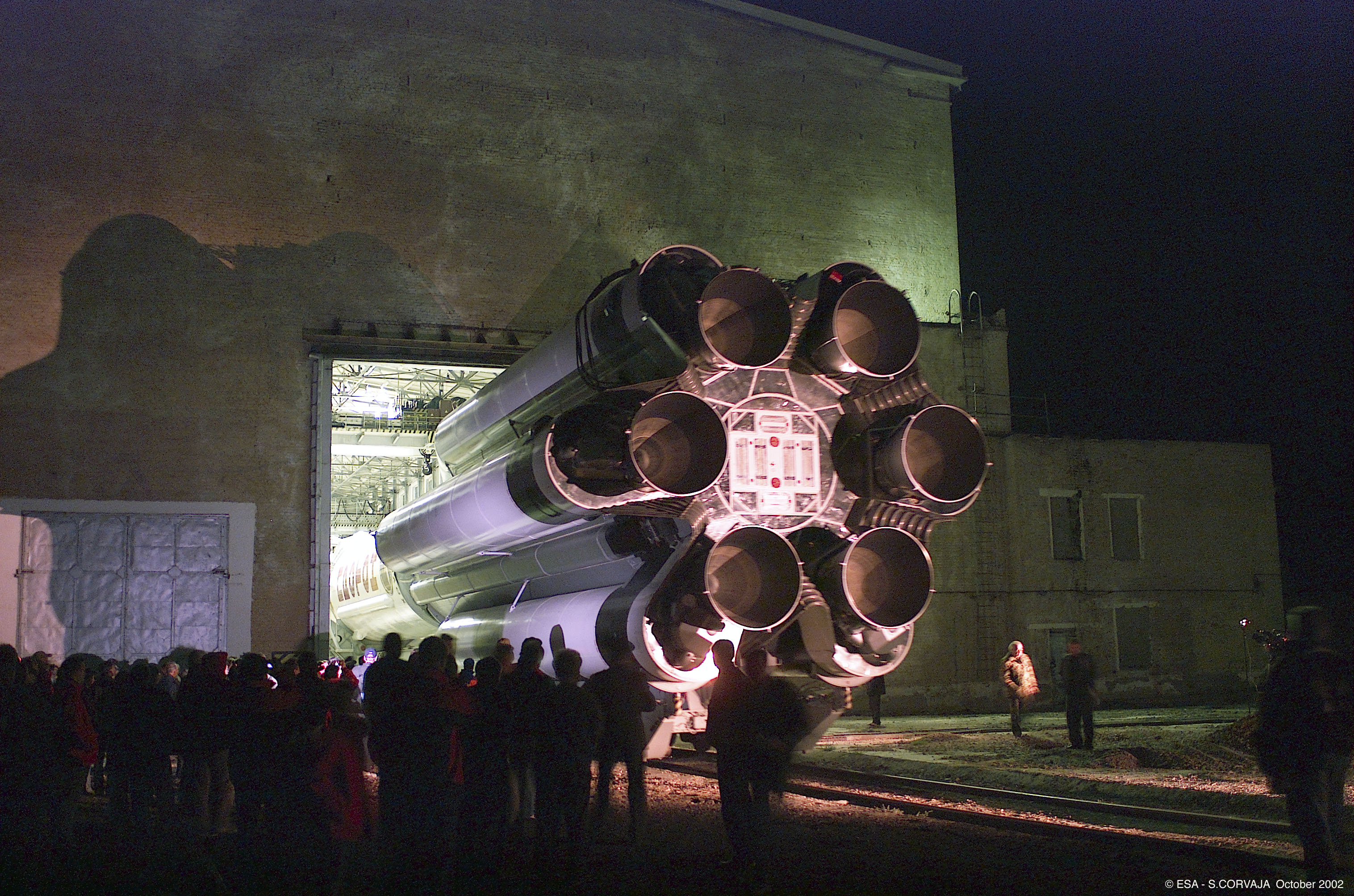
Look at the blankets over the rocket: http://rocketry.files.wordpress.com/2011/09/proton3.jpgMore of the business end: http://rocketry.files.wordpress.com/2011/09/proton2.jpg
Here it is just as it is being lifted and the rail trucks still on the tracks: http://news.3yen.com/wp-content/images/proton350x218.jpg
This photo is really big and gives good detail of the motors: http://sci.esa.int/science-e-media/img/25/35066.jpg
Here is another paint scheme: http://4.bp.blogspot.com/_HkkJKGa-ZX8/TQOkN28SgAI/AAAAAAAAALE/yfhx8RpuC0s/s640/04.jpg
I look at this website, go down to the second photo where stages are being mated and see details of the 1st stage and what it looks like before the fairings are put on around the fuel tanks: http://orbiterchspacenews.blogspot.com/2010/12/proton-to-return-to-flight-in-december.html
Here is a picture of a Proton model going off at Plaster Blaster 9 : http://freeimagefinder.com/detail/5155594028.html
And some more detail of the motors: http://www.sciencephoto.com/image/136241/530wm/C0073258-Proton-M_rocket_engines-SPL.jpg
That is all I can do right now.
2012-01-20 at 2:33 am #55228smashburn
Hey guys! I need phone numbers for everyone if possible. I hope to meet with Scott on Sat about using his hanger in Longmont for the build. We’ll need to help him move some stuff abound and make room. Possibly some of you could join us and we could meet and go over my plans for the project. I will have all the parts gathered so far with me. We can get a good inventory and see if there are any ‘immediate’ needs.
PM your number, don’t post on the forum.
I -may- have to work Sat morning so I’m unable to set a time yet. I’ll know for sure tomorrow night.
Also, I am rebuilding my old website and uploading all the pics. I have tons from the Delta II build. You’ll get an idea of what’s in store by looking at them. It’ll take a while for me to get them all up.
Thanks!!
Steve
2012-01-20 at 3:58 am #55229SCOTT EVANS
“Put a blue hardhat on that man and keep him away from the tool chest.”
But I would like to help out (live in Fort Collins) – and as you implied at the annual meeting – learn by watching the big boys. I can sweep floors, change lightbulbs, take out the garbage (my wife can vouch for that), and recently learned how to operate a can of spray paint. Unlike many in this economic climate, I am fortunate enough to be gainfully employed, so have a little disposable income that I could donate to the cause.
Let me know how I can help.
Well now!!!…………. I have 2 light bulbs that need changing! Those 200 watt things they are trying to outlaw! 🙂 Need a step ladder…… A BIG ONE! say 15 or 20 feet. Broom? I have one. You can show me how to push it! Do you have a tooth brush? 😉
2012-01-20 at 4:55 am #55230RichWallnerParticipantI have a copy of the “International Reference Guide to Space Launch Systems”, and I’ve scanned the pages that seem to be relevant to the project and uploaded JPGs to Picassa:
You should be able to zoom in & read the text if you click on the magnifying glass icon at the top of each image.
This guide (page 3 of what I scanned) describes the reason for the unusual booster engine configuration:
“The Proton first stage consists of a large central core oxidizer tank surrounded by six smaller fuel tanks. These are easily mistaken for strap-on boosters, but in fact they are an integral part of the first stage and do not separate. This distinctive design stems from early requirements for transporting Proton. The vehicle stages had to be manufactured at a central factory, then shipped by rail to the launch sites. The maximum length and diameter of the components were therefore limited by existing railway tunnels and other rail infrastructure. However, performance requirements dictated that the first stage would exceed these dimensions, thus requiring that it be manufactured as more than one element…”
2012-01-20 at 4:56 am #55231BEAR
Anybody desiring to go to Longmont for a meeting and who lives in Fort Collins or this vicinity is welcome to ride with me. I am starting in Wellington and headed south. I guess I have room for up to 4. Send me a PM and we can trade phone numbers, etc.
2012-01-20 at 5:27 am #55232smashburn
I’d just like to say that Steve Mashburn (smashburn) took on a bare L1 (me) when he proposed the Delta II project. I had some skills, but had never been involved in anything like that level of size or complexity. He knows how to execute a large project and I highly recommend it as what may well be one of the seminal experiences of your rocketry career – it certainly was for me. I learned a LOT and had a great time along the way. When it finally flew, my heart was in my throat and I was jumping up and down like a 5 year old. An experience not to be missed.
I’m here and available if needed.
Warren
Thanks Warren, I appreciate the kind words and support. I feel really good about this project and the group that’s forming .. real good energy. Hopefully we can get together on Sat at Scott’s and officially kick this off. I’ll know tomorrow if I have to work Sat .. but I don’t think I will.
2012-01-20 at 3:16 pm #55233SCOTT EVANS
I have a copy of the “International Reference Guide to Space Launch Systems”, and I’ve scanned the pages that seem to be relevant to the project and uploaded JPGs to Picassa:
You should be able to zoom in & read the text if you click on the magnifying glass icon at the top of each image.
This guide (page 3 of what I scanned) describes the reason for the unusual booster engine configuration:
“The Proton first stage consists of a large central core oxidizer tank surrounded by six smaller fuel tanks. These are easily mistaken for strap-on boosters, but in fact they are an integral part of the first stage and do not separate. This distinctive design stems from early requirements for transporting Proton. The vehicle stages had to be manufactured at a central factory, then shipped by rail to the launch sites. The maximum length and diameter of the components were therefore limited by existing railway tunnels and other rail infrastructure. However, performance requirements dictated that the first stage would exceed these dimensions, thus requiring that it be manufactured as more than one element…”
I can see the Russian scientist coming out in here.
Trying to distract from our um……..”BOOSTER” separation. 😉 -
AuthorPosts
- The forum ‘Archives 2012’ is closed to new topics and replies.